Radio Controlled
When it comes to RC Models, what tickles my fancy are scale airplane models, from a kit or scratch build. Building the model is half the joy, as flying is is the other half. I have to admit the fact that scale planes where one has put a LOT of effort into details is not what you want destroyed. And since all model planes is a potensional crash waiting to happend, it can often be scary to set a newly built bird free in the air.
Stick and tissue RC modelling
When it comes to Radio Controlled Models, my preferences are to scale planes, from a kit or scratchbuild. Building the plane is half the joy, as flying them is the other half. Only problem I have to admit is the fact that scale planes where one has put a LOT of effort into details, is that you really dont want to crash them. And since all modelplanes is a potensional crash waiting to happend, it can often be scary to put a newly built bird into the air.
I am using a ClearView RC Simulator in order to add to my skills as a pilot, and I can recommend this simulator to everyone. The price is cheap, and it works perfectly. I 'd wish there would be more models to choose from tho, but more can be downloaded from the internet.
The aviation history and technical solutions I find as interesting as with old cars and bikes. The story behind the 9 cylinder rotating Gnome engines of the first years after 1900, is as intriguing as the effect they had on the planes and the way the pilots did fly them. Take your time to look at the last video of the Sopwith Camel on the end of this page where they start the rotating radial engine, and how it affects the plane. Also, take your time to look at the video where they start a more modern radial engine, which do not rotate itself, but have a rotating axle inside. Very early engines were rotating themselves to avoid heavy flywheels to keep the engines running in the already heavy planes. Whereas later radial engines had the engines mounted in the plane with a rotating axle instead.
Being a petrolhead I am very easily impressed with engines, and I urge you to look at these few ones: 14 cylinder model radial engine (excellent sound!), V12 Modellmotor RC Engine, and also a Miniature Model v8 engine. A fully working Ferrari 312 PB replica scale model where ALL the cars parts have been hand made by a very dedicated French man. Airplane with two homemade RC Twin Pulse Jet engines is very noisy, but really very cool.
Do not mistake any of these pictures as pictures of the models I have. Since they are not. I make these pages for you to see details and examples of the planes how they will look when done. Also the linked images, pages and videos are included on this page for your entertainment only. I will however in time add real flight pictures, and comment these with an appropriate text in due time. If anyone recognices their own pictures, and want them removed, please contact me, and I will remove them immideately.
I present on this page the planes I have in wait or in progress to be built. I am not particulary fond of war birds, but I like planes with a lot of details. And somehow this results in planes from yesterday as my preferance. I have probably built around 20 planes in my life. All from rubber powered valnut scale to bigger planes, RC and line control. All of which either has been destroyed by flight or storage. The one I kept the most years was a 42 inch wingspan line control balsa Fokker D7 Biplane, which I never deared to fly!
As flight controls I have the Futaba 7CAP/CHP dual airplane/helicopter 7 channels set and a DSM2 Spektrum DX7E.
Lately I have been flying with a tiny Mini DV 80 DVR camera mounted on my Easy Glider. Check my channel at Youtube to see some RC videos and videos taken from flying Ultralights.
Great Planes KIT - Pete'n Poke
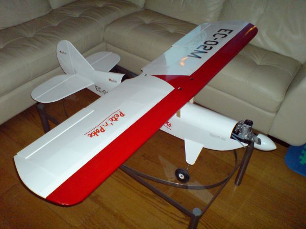
The Pete'n Poke model as I built it.
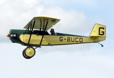
The Pietenpol Air Camper plane flying.
The Pete'n Poke is modeled loosely on the 1920s-era, Model "A" Ford engine-powered Pietenpol Air Camper homebuilt and the popular Great Planes Slow Poke.
The Pietenpol Air Camper is a two place, tandem seat, open cockpit plans-built monoplane. A Ford Model A 4 cylinder engine converted for flight powers the aircraft. This is a wood aircraft constructed from spruce and plywood. All fittings are fabricated from steel flat stock. The motor mount, landing gear and wing struts require welding. The Air Camper was intentionally designed to be simply constructed with a minimum of tools. The wings are covered with fabric and varnished. Bernard Pietenpol designed the plane so that the average person in the 1930’s could build and fly it from almost any off-airport field. Even after seven decades, there are still loyal followers of the Pietenpol designs, building and flying low and slow open cockpit aircraft and having a great time doing it.
Video of the real Pietenpol Starting here. And if you want to fly it, this is the link to click.
The Pietenpol Air camper is a very historical airplane, and you can read more about the planes and the Pietenpol family.
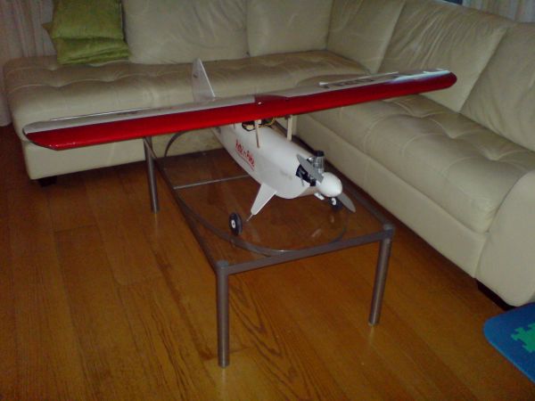
The Pete'n Poke model seen from the front.
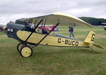
Pietenpol Air Camper on the ground.
Specifications:
Wingspan: 59.5 in (1510 mm)
Wing Area: 809.2 in² (52.2 dm²)
Weight: 5.75 lb (2.6 kg)
Wing Loading:16.4 oz/ft² (50 g/dm²)
Length: 47 in (1195 mm)
Engine: 2-stroke .40-.46 cu in (6.5-7.5cc) or 4-stroke .40-.52 cu in
(6.5-8.5cc)
The Pete 'n Poke kit will be the one I plan to fly the most. The plane offers
smooth, slow flight with the potential to perform all basic aerobatics. Its
versatility is matched by vintage aircraft looks - including easy-to-install
cabane struts - for a distinctive "Sunday" model that's a treat to fly ANY day
of the week.
A video of the flying model can been seen here too!
The Pete'n poke will be equipped with a OS FS 52 Surpass engine.
Click to see pictures and
my review of this model.
MIDWEST MODELS KIT - Giles 202 27% (Box opened!)
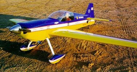
Giles 202 - Model from the front.
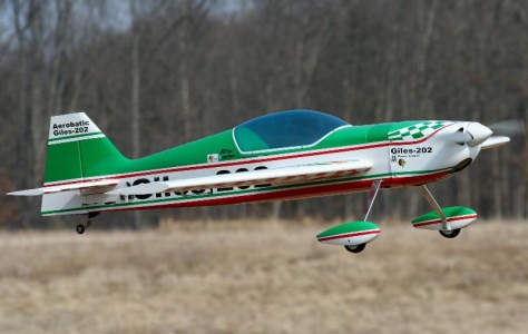
Giles 202 model flying, from the side.
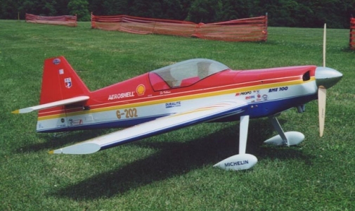
Giles 202, nice color combination.
The AkroTech Giles G-202 is a serious aerobatic aircraft, flown by top competition pilots worldwide. This two seat variant is based on the single seat G200 that was first produced in 1992.
Built of advanced carbon fibre materials, the fuselage contains no welded steel components at all, and this makes the aircraft relatively light. Even with a simple four cylinder Lycoming IO-360 engine, the top speed is 253 miles per hour, with a cruise of around 200.
One pilot has described the G202 as "reckless abandon capable: It's a plane that doesn't limit the pilot in anyway."
Lloyd Beaule, a former Canadian National Aerobatic Champion said of the Giles: "I had to look under the cowl and make sure there are were four cylinders under there! The performance of the airplane is absolutely amazing. The controls are so well harmonized, it leaves you speechless. This is a wonderful aerobatic airplane...
The Giles 202 is an acrobatic plane capable of almost everything.
This video
shows the real plan in the hands of a skilled pilot. The plane is a
quick
pylon racer, whith very cool sound and looks. The plane looks and sound
really excellent on low passes.
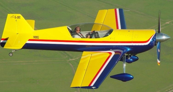
Some of the videos above is of the Inverted Downunder airplane, and I like the color combination of it.
Giles 202 model, different colors.
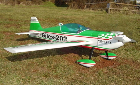
Giles 202 Model parked.
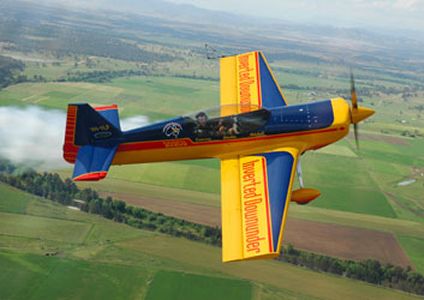
Giles 202, Inverted Down Under Plane.
Specifications:
Wing Span: 72 in (1830 mm)
Wing Area: 960 sq in (6194 cm²)
Length: 60 in (1520 mm)
Weight: 12.5 lbs (5.7 kg)
Engine: 1.08 - 1.50 2 - stroke (17.7 cc - 24.6 cc 2 - cycle)
1.20 - 1.80 4 - cycle (19.7 cc - 29.5 cc 4 - cycle)
The Giles 202 is an acrobatic plane, maybe not perfectly suitable for 3D
flying. It is on the heavy side with its 5.7kg.
My plan was to fit a Supertigre G4500 which I already own to it. The engine is heavy, and the plane is already heavy so it seems to be a bad choice. I have been back and forth about using the 45cc Supertigre G4500 and have come to the conclusion that the 45cc will have to go in favour for a 24cc Supertigre G-2300 instead.
I like the rather HUGE 45cc on the shelf, but I have to admit, there will not be build any planes in this house where this beast of an engine would fit...
The plane performs excellent on a O.S 1.60 tho, And it looks nice in the air with a smoke system as well!
What colors to use on the plane? Since I like Scale Planes, I think it will be covered as the "Inverted Down Under" plane as linked to the left, and as shown in the image of the real plane to the bottom right.
Click to see pictures and my review of this model.
Micro Pitts - Depron Scratchbuild 30cm wingspan
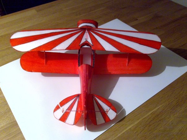
Micro Pitts model from the rear.
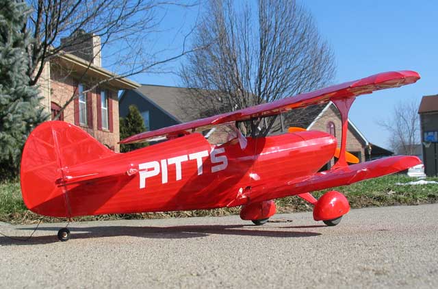
The real Pitts Special.
Curtis H. Pitts began the design of the Pitts Special in 1942 in Jacksonville, Florida. The first Pitts Special aircraft, powered by a 90 hp Franklin engine, flew in 1944. For the following 25 years, the Pitts Special was constructed as a homebuilt only. During this period, the design was continually refined to improve aerobatic performance. By 1962, the standard engine had been increased to 180 hp, and in 1966 a symmetrical airfoil was added to make inverted flight characteristics similar to normal upright flight characteristics.
In 1970, a manufacturing operation known as Pitts Aerobatics was started in Afton, Wyoming. The first Pitts Special S-2A was produced in Afton in 1971. During the 1970's, most Pitts Special versions were Type-Certified under the requirements of FAR Part 23 in the Acrobatic Category. Since then, the Pitts Special S-2B has received Type-Certification and has become the most popular version of the Pitts Special line in current production.
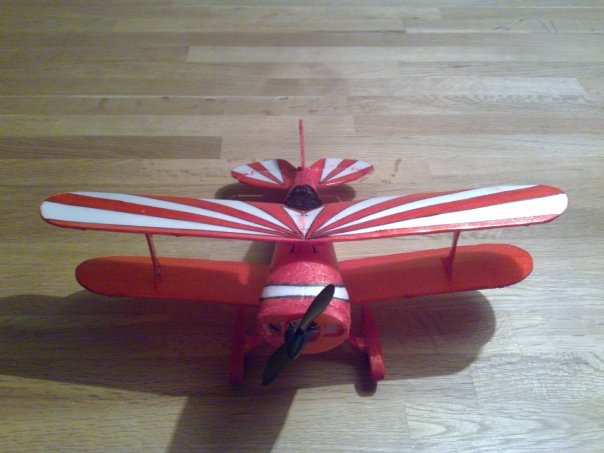
Micro Pitts model from the front.
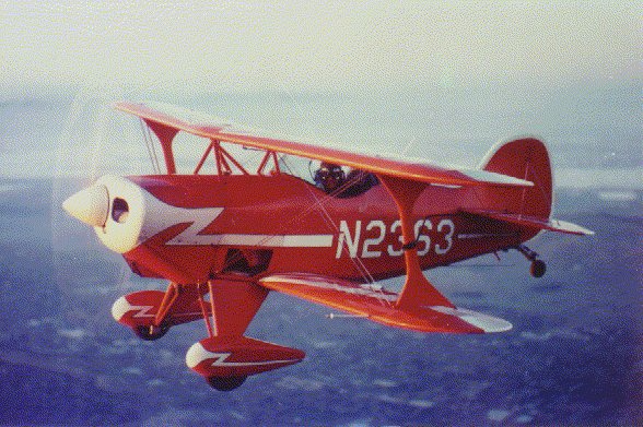
The real Pitts Special.
Specifications:
Weight: 23 gram
Wingspan: 300mm
Engine: Miniature Brushelss
This Micro Pitts was very tempting to build when i found Chris O'Rileys plan
for the micro Pitts Balsa model.
I have however built the plane in Depron since it is a wee bit more crashsafe. And it flies beautifully, and does indeed take crashes well.
Click here to see the model in flight.
Click to see pictures and
my review of this model.
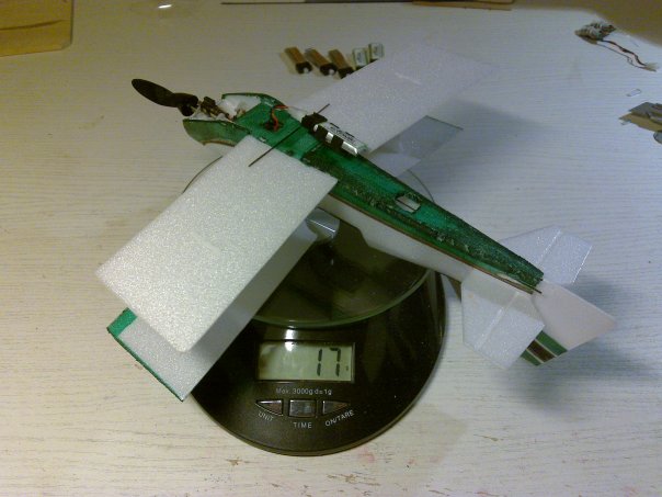
Micro Ultimate - Depron Scratchbuild 25cm wingspan
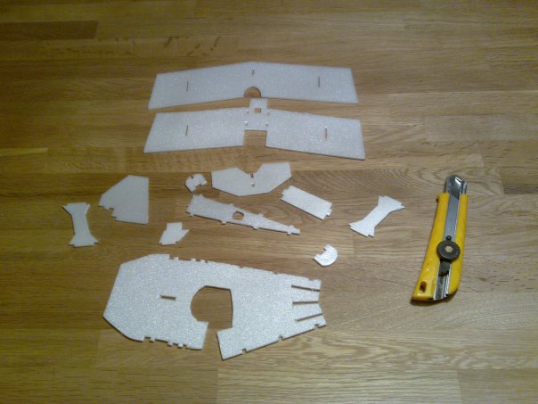
Micro Ultimate parts made from hamburgertray depron.
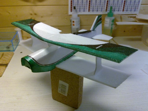
All mounted together.
The Micro Ultimate is made on the same base as the Micro Pitts above. The plane consists of few parts and is very light. The radiogear comes from the Vapor plane, with a 6mm shortened prop. Total weight is 17 grams, and the thrust from the prop is approximately 16 grams.
And it flies rather well actually, maybe not a trainer, but still flyable for a rookie like me.
Coloring are done with permanent markers.
All mounted together.
Specifications:
Weight: 17 gram incl 74mah Lipo battery
Wingspan: 25 cm
Engine: Vapor brushed motor
The flying qualities of this micro model is good, specially for its size and
the materials used. I used a clear lightbulb plastic container in order to make
a canopy, works very well.
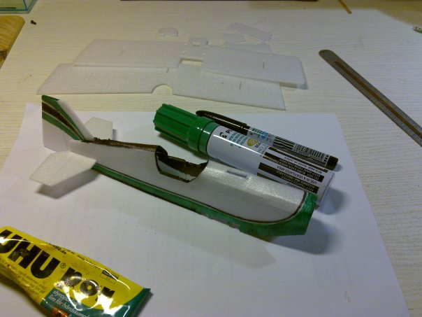
1:40 Scale Sopwith Camel built using balsa stringers and covered with inkjet printed paper
Half the elevator is completed. I use tweezers to make this plane, since the elevator is approximately two pins wide. The plane is in general made with spars and stringers of balsa. This makes is ultra light weight. On top of this i will glue coating paper, also very very light. And surprisingly strong actually!
Mounted the fuse and lower wings with the fin and the elevator. Even made two small machine guns to be mounted on the "hump" in front of the seat. This hump is what made the plane earn its name btw... the Sopwith Camel is because of the hump covering the machine guns.
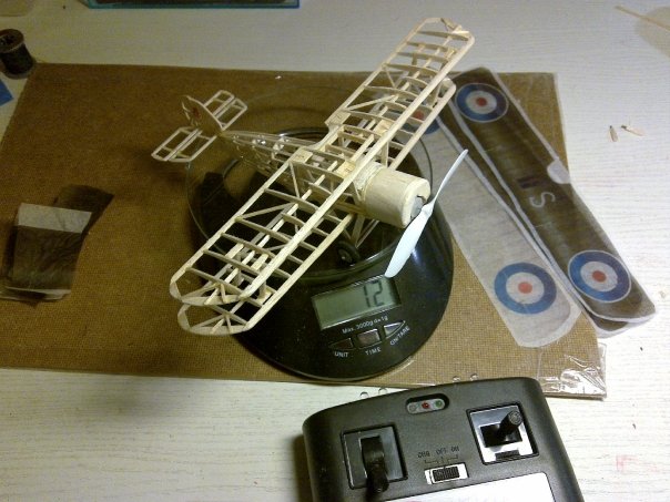
Weight ended up to be 12 gram with wheels and undercarriage. Paper will add another 1/2 gram, but I still believe 12 gram will be the end. The extended nose added at least one gram, also the undercarriage. So the hoped for 9 grams was busted badly... 4 grams of radiogear and 7 grams of plane i guess is a good achievement. 7 grams is not much, but adding a couple of cables and some glue... voila you have one more gram!
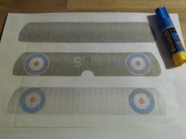
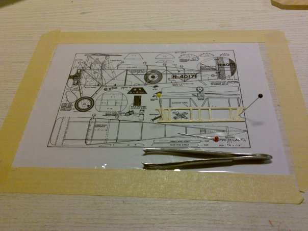
HOW TO PRINT COVERING TISSUE PAPER:
It takes some adjusting to size, and percent of original before the prints
are just a few mm larger than the wings.
But after a few trials and errors, a print on a normal sheet of paper can be
used as a carrier for the ultrathin tissue paper which to be used on the
plane.
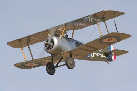
The Sopwith Camel was a British World War I single-seat biplane fighter introduced
on the Western Front in 1917. It had a combination of a short-coupled fuselage, heavy,
powerful rotary engine and concentrated fire from twin synchronized machine guns.
The Camel was credited with shooting down 1,294 enemy aircraft, more than any other
Allied fighter in the First World War.
See the Sopwith Camel live in flight here in this video.
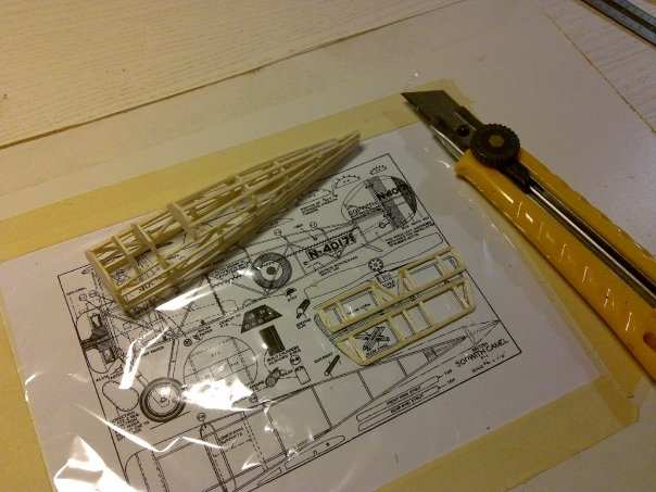
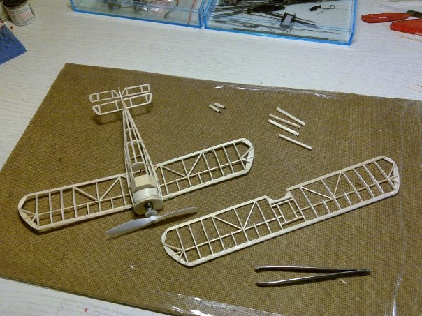
Very very small build this. Halfway done with the fuse here, and completed with the aileron. I sort of like this build... small parts indeed, and tweezers for every job.
The Camel has a very stubby nose due to the extremely heavy Gnome rotary engines. (Look up videos of the Sopwth Camel on youtube! The whole engine were rotating, and it was on full throttle all the time, speed controlled by turning engine on and off with ignition only, very cool!) Anyway, these were heavy cast iron engines, and it gave the Camels it short nose. (To simplify the build, this Camel did get a nose job.)
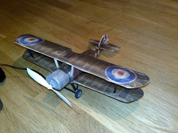
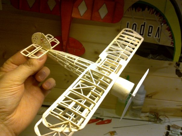
Build completed!
I did think and have heard that paper with inkjet ink, which have been sprayed with
fixative should be waterproof. For me that was not the case tho... Water damage from
shrinking the paper is under the plane tho, so it is fine, even if a little annoying.
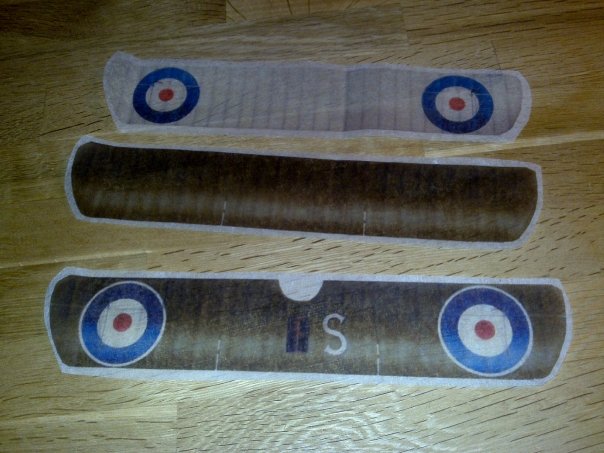
After printing, use scissors and cut the printed patterns out. They are surprisingly detailed and unmarked from the spray of ink. For the ones wondering in detail how this is done, click HERE. (You need proper airplane dopeable tissue paper, an inkjet printer and a spraycan of fixatif to cover your airplane this way)
Specifications:
Weight: 12 gram
Wingspan: 4 inches
Engine and radiogear: 2 channel IR, taken from a donor toy.
Testflying this model revealed that it was a bit light on the nose. So it works
best as for display than flying. I tried to create a similar rc plane like
these on
YouTube, but I think one have to choose both radiogear and materials a bit
more than scavenging a toy like I did.
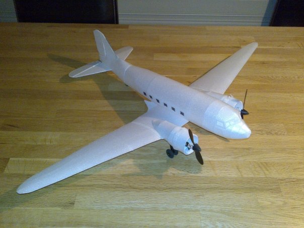
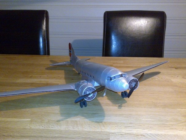
Micro DC-3 twin engine
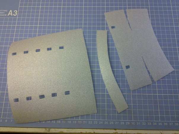
Have you ever built a cardmodel plane? This build is the same. Depron when thin as 0.6 mm and 1.2mm is very flexible and bendable and can be folded like paper.
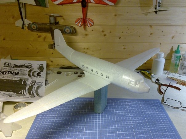
Wing is completed and test fitted to the fuselage. All seems good with snug fits. Wing is HUGE for the weight. Plane without hardware is 15 grams!
lane ended up at 36 grams including
battery. Not bad at all!
The props are Kyosho Citabria props, and i have to cut off a couple of mm of
the tip since they are so large that the almost touch the
fuselage.
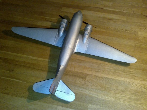
Unmistakeable DC-3 backwards swept wings, complete with dummy and fake radial engines. Making cardmodel flying planes are fun!
The Douglas DC-3 is an American fixed-wing, propeller-driven aircraft whose speed and range revolutionized air transport in the 1930s and 1940s.
Because of
its lasting impact on the airline industry and World War II it is generally
regarded as one of the most significant transport aircraft ever made. Many
DC-3s are still used to this day in all parts of the world.
See the Dakota of Norway in flight here in
this video.
You can read more about this plane at Dakota Norways homepage
A friend of mine made this plane first (Check this video out with him flying it!) And it looked very cool, so I did the same!)
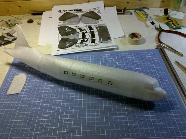
Here is the first fuselage parts glued
together. A little experience is needed for all to be correct. But not to
much. I use Uhu Por which is a contact glue. And this means one have to pay
special attention to put the piece on correctly at once.
Contact glue is instant bond when pieces are put together. So putting things
wrong will mean permanently wrong.
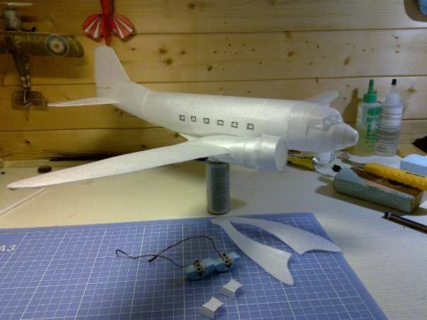
And here is the tail also done.
Adding enginepods here and comleted the motors and ESC for mounting.
I made the wings with a pine 2mm by 2mm stringer in order to get som
stiffness. 1.2mm depron is not exactly stiff.
This worked like a dream, and the wings are sturdy and strong.
Looking much better after painting. Very
thin sprayed paint dont add much weigth.
Dakota of Norway colors, only lettering left to do.
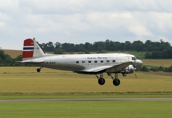
This the plane which i want to use for colorisation and markings. It is an old Dakota (DC-3) which is norwegian with the marking LN-WND.
Specifications:
Weight: 36 gram
Wingspan: 63 cm
Engine and radiogear: 4 channel Kyosho Minium.
Built from Fiddlers Green Plans with durobatics polysterene foam sheets, AUW
36g, wingspan 63cm, RC-quipment from Kyosho/Parkzone Minium Cessna.
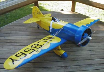
Scratch build - Mister Mulligan
Mister Mulligan model, from the front.
Mister Mulligan parked.
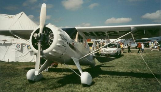
Mister Mulligan from the front.
Ben Howard was one of America's premier aircraft
designers and competitive pilots during the mid-1930s. He built a series of
airplanes carrying the DGA, or "Damn Good Aircraft," logo. The most famous was
Mister Mulligan, the racing DGA-6 that captured both the Bendix and Thompson
trophies at the 1935 National Air Races. Howard was the only pilot that achieved
that feat in the same year. The Bendix Trophy was a cross-country race from the
west coast to the site of the National Air Races in Cleveland, Ohio. At the
National Air Races, the Thompson Trophy was given to the winner of the unlimited
division in close-course pylon racing. Ben Howard and Gordon Isarel flew the
DGA-6 in the Bendix and won with a speed of 238.70 m.p.h. Harold Neumann racing
the DGA-6 recorded a 220.19 in winning the trophy. Howard's DGA-6 was the only
racer during the golden age of airshows to evolve into a successful commercial
production aircraft. It was first as the DGA-8 & -9 and then the DGA-11 &
12.
Mr. Mulligan's engineering advantage was it's low-drag airframe and the use of
the 850-horsepower Pratt & Whitney Wasp radial. The four-seat Mister
Mulligan's commercial roots made the difference in the Bendix race. Ben Howard
and Gordon Isarel beat Roscoe Turner by less than a minute, thanks to two fewer
fueling stops in the race from Burbank, California to Cleveland, Ohio. Mister
Mulligan broke a three-year streak of wins in the Bendix for Wedell-Williams.
Howard and his DGA-6 replaced Williams-Williams as the star of aviation by
outlasting defending champion Turner in the Thompson race when he was forced out.
Newspapers chronicled the 1935 event as the "Ben Howard National Air Races".
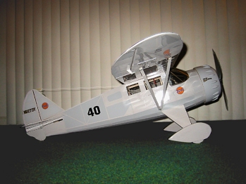
Mister Mulligan model from the side.
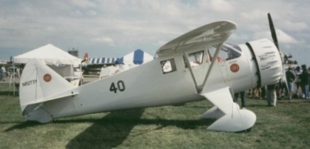
Mister Mulligan from the side.
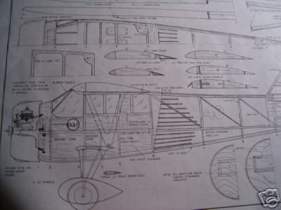
Mister Mulligan plans.
Specifications:
Wingspan: 41.5 in (1041 mm)
Wing Area: 328 in² (21 dm²)
Weight: 2.37 lb (1,07 kg)
Length: 35 in (878 mm)
Engine: 2-stroke .10-.25 cu in
I have two plans for this model. One has a wingspan of 104 cm and one has a
wingspan of 130 cm.
A great flying plane, Easy to fly, tracks straight and looks simply great in
the air.
Here is a link to a video of a 1/4 scale Mr. Mulligan flying
My 130 cm wingspan version will sport a OS Max 46 2 stroke engine where the 104 cm wingspan version will have the OS MAX 10 2 stroke engine which have been hiding away in my RC stuff in 15 years! If I build both planes, or which one if not is yet to decide.
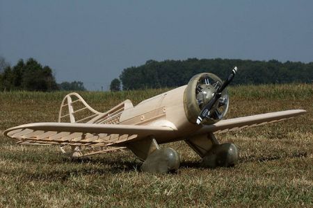
Scratch Build - Gee Bee Model Z Sportster 1/4 Scale Plans
The Gee Bee Model Z Sportster from the side.
Gee Bee Model Z Sportster plane from the side.
Gee Bee Model Z Sportster RC Model built.
SEPTEMBER 7, 1931. Eight racing aircraft, some of the fastest land planes in the world, were lined up for the start of the Thompson trophy race at Cleveland, Ohio. The field consisted of Lowell Bayles in a Gee Bee Model Z, Jimmy Doolittle in his Laird "Super Solution", Jim Wedell in a Wedell-Williams Special, Ben O. Howard in his Howard "Pete", Dale Jackson in a Laird "Solution", Bill Ong in a Laird Speedwing, Ira Eaker in a Lockheed Altair, and Bob Hall in a Gee Bee Model Y. The Thompson was a ten lap race of 100 miles and was the climax of the National air races.
As the starter's flag dropped, all conversation was lost in the roar of the eight powerful engines as the entries blasted toward the first pylon one mile away. Doolittle was the first pilot to make the turn but soon his "Super Solution" began trailing black smoke from a broken piston. Gamely he tried to hold his position. On the second lap, Bayles in his Gee Bee Z, "City of Springfield", took the lead. Dale Jackson had a narrow escape from tragedy as he brushed a tree, but he continued to race. Bayles continued to extend his lead. On the seventh lap. Doolittle was forced to retire. Bayles roared across the finish line at an average speed of 236.2 mph, culminating a week of triumphs for the Gee Bee team. Bob Hall finished fourth in the Model Y at a speed of 201 mph. The Gee Bees had nearly dominated the 1931 National air races and the Model Z had won every contest in which it was entered.
The film Rocketeer had an opening sequence where the Gee Bee Z did fly.
But that plane is now on display at the Museum of flight in Tukqila, Washington.
However there have been built a new replica of the Gee Bee Z which is
flying.
Here is some nice
footage shot air to air of the same machine.
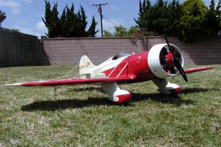
The Gee Bee Model Z Sportster from the front.
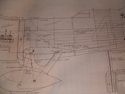
Gee Bee Model Z Sportster RC Model plan.
Gee Bee Model Z Sportster RC Model built.
Specifications:
Wingspan: 71,5 in (1794 mm)
Weight: 12 lbs (approx 5300 g)
Length: 47 in (1180 mm)
Engine: .91-1.08 cu in (15-18 cc) 2-str or a 1.20 cu in (20 cc) 4 str
The drawings of this very nice plane is in scale 1/4 made by Henry Haffke.
The model need a radial engine, both for sound and for looks. And the Saito 5 cylinder engine engine or a7 cylinder Robart R780 Radial might fit.
Or maybe it will be a 3W twin engine? The Gee Bee Z model need an engine which complement it with a proper sound I think.
RC model Gee Bee Model Z in flight here. The R1 and R2 racers were very similar to the Z model in looks.
They say this plane is the most difficult to fly. And they might really be correct. I have tried to fly it in the RC simulator, but it really needs so high landing speed that there is a very definitive chance of total crash if flown. So it might be built, but never to be flown.
Here is a video with the Z flying where the pilot have added landing instructions.
By watching this maiden flight, one get the distinct feel that this plane is not the easiest to handle.
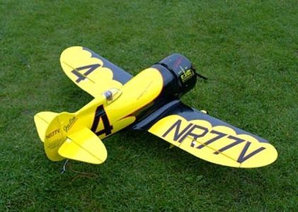
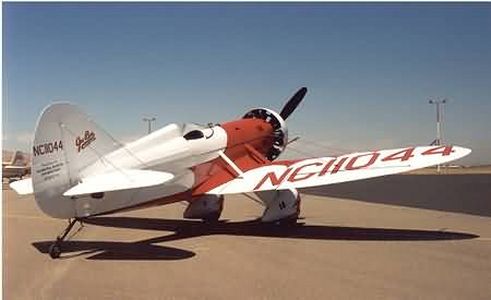
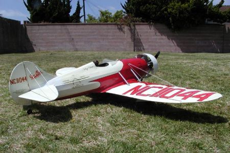
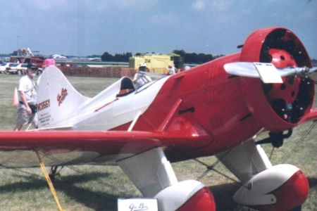
Scratch Build - Gee Bee Model E Sportster 1/4 Scale Plans
The Gee Bee Model E Sportster from the rear.
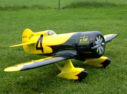
Gee Bee Model E Sportster RC Model from the rear.
Gee Bee Model E Sportster RC Model being built.
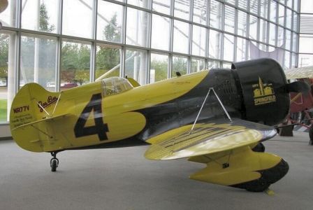
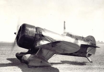
Granville Brothers Aircraft was an aircraft manufacturer in operation from
1929 until their bankruptcy in 1934. They were located at the Springfield
Airport in Springfield, Massachusetts. The Granville Brothers, Zantford,
Thomas, Robert, Mark and Edward are best known for the production of the three
Gee Bee Super Sportster air racers. The small, flashy Granville Brothers
Aircraft E Sportster embodies the spirit of sport aviation in the early 1930's.
Over a period of just four years, the five innovative Granville brothers of
Springfield, Massachusetts, led by chief designer and oldest brother Zanford
Granville, went from building simple biplanes to producing highly advanced race
planes that set world land plane speed records.
The Gee Bee Sportster offered their pilots the thrills of a high-performance
aircraft, without the high costs or dangerous flight characteristics of a
specialized race aircraft. Advertised as having "no rivals in performance,
maneuverability or beauty," the brothers marketed their Gee Bee Sportster's
with a number of different engines for a cost of less than five thousand
dollars.
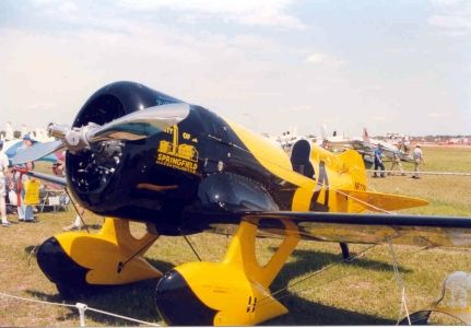
Scott Crosby built the Museum's Gee Bee E Sportster replica. The construction
process lasted eight years and two months. Crosby was able to obtain the same
FAA registration number for his Gee Bee replica once assigned to the first
Granville Brothers E Sportster.
The Gee Bee Model E Sportster from the front.
Gee Bee Model E Sportster RC Model from the front.
Gee Bee Model E Sportster RC Model in a different colour scheme.
Specifications:
Wingspan: 71.6 in (approx. 1800mm)
Fuselage Length: 47in. (approx. 1180mm)
Weight: 5334 gr
Motor Size: 0.90cu.in. - 1.10cu.in. 2-str / 1.20 - 1.60 4-str
RC- Functions: Rudder, Throttle, Elevators, Ailerons
The drawings of this very special model is in scale 1/4 made by Henry
Haffke.
The model need a radial engine, both for sound and for looks. And the ASP FS400AR engine or a Saito FA-90R3 Radial might fit.
Or maybe it will be a OS FS 120 with a Müller spark ignition module? With this ignition module and a rimfire spark plug does make the sound better when run in high revs.
RC Gee Bee Model E Model in flight here.
Scratch Build - Westland Lysander 1/8 Scale Plans
The Westland Lysander from the side.
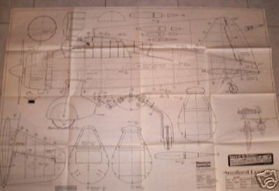
P.Kriz Westland Lysander Plan.
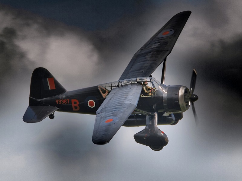
The British Westland Lysander was a slow-flying high-wing two seat monoplane, lightly armed, and designed pre-war to cooperate with ground forces. No.225 Squadron was reformed on the 11th October 1939 from No..614A Squadron. Its Lysanders were mainly used in Army exercises except for some coastal patrols conducted from June 1940. They were easy targets for German fighters and suffered heavy losses in France and Belgium. They were soon relegated to second line duties where the STOL capabilities of the aircraft was used to their full potential
The first Lysanders entered service in June 1938 equipping squadrons for "Army Co-operation" and were initially used for message-dropping and artillery spotting. When war broke out in Europe, the earlier Mk Is had been largely replaced by Mk IIs, the older machines heading for the Middle East. Four regular squadrons equipped with Lysanders accompanied the British Expeditionary Force to France. These were put into action as spotters and light bombers. In spite of occasional victories against German aircraft, they made very easy targets for the Luftwaffe unless escorted by Hurricanes. Almost half the Lysanders operating in and over France were lost and, with the fall of France, the type was quickly withdrawn from its army co-operation role. Back in England some went to work operating air-sea rescue for RAF pilots in the English Channel. Fourteen squadrons and flights were formed for this work during 1940/1941, dropping dinghies to downed pilots.
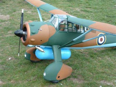
The Westland Lysander seen as a model.
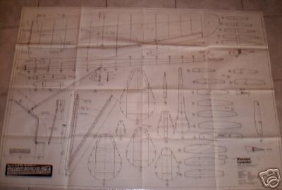
P.Kriz Westland Lysander Plan.
Specifications:
Wingspan: 76in (approx. 1900mm)
Fuselage Length: 46in. (approx. 1160mm)
Weight: 2100gr
Motor Size: 0.60cu.in. - 0.90cu.in. 2-str / .91 - 1.20 4-str
RC- Functions: Rudder, Throttle, Elevators, Ailerons, Flaps
The drawings of this WW2 model was made by P. Kriz, and it is a large airplane
in 1/8 scale.
The model need a radial engine, both for sound and for looks. But what about a 2cylinder V-Twin from Enya engine?
The plans for this model is really awesome. The plane is big and looks really excellent. The wing shapes and size of this plane indicates it is a plane which can fly at really low speeds. And maybe with flaps on it will even be able to land at scale speed?
I have always found the Westland Lysander to be a beautiful plane since I was a kid. I remember getting a Revell moulded kit at an early age, which i did paint and build. As a model the airplane is docile and a good flier. Here is some footage of a RC model flying.
Video of the real Westland Lysander fly by here. The Westland Lysander can be looked at in detail here in this link.
Scratch Build - Sopwith Camel 1/6 Scale Plans
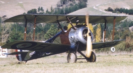
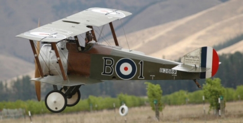
The real Sopwith Camel from the side.
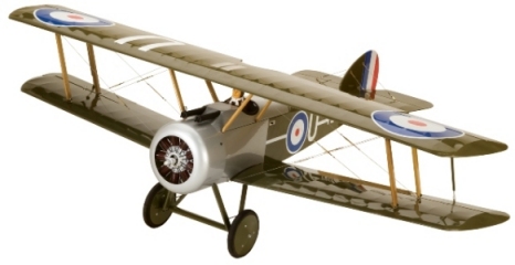
Sopwith Camel RC Model flying.
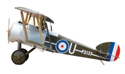
Sopwith Camel RC model from the side.
Intended as a replacement for the Sopwith Pup, the Camel prototype first flew in December 1916, powered by a 110 hp Clerget 9Z. Known as the "Big Pup" early on in its development, the aircraft was armed with two .303 in (7.7 mm) Vickers machine guns mounted in the cowl, firing forward through the propeller disc. A fairing surrounding the gun installation created a hump that led to the name Camel. The top wing was flat - but the bottom wing had dihedral, so that the gap between the wings was less at the tips than at the roots.
The type entered squadron service in June 1917 with No. 4 Squadron of the
Royal Naval Air Service, near Dunkirk. The following month, it became
operational with No. 70 Squadron of the Royal Flying Corps. By February 1918,
13 squadrons were fully equipped with the Camel. Approximately 5,500 were
ultimately produced.
Video of the real Sopwith Take off here. Sopwith Camel fly by with a Fokker here in this
link. The Engine of the Sopwith Camels are running on full throttle all the
time, and speed is controlled by the ignition magneto. This is very audible in
both videos.
This is very much audible in this video where you get to experience the ignition speed control, with some very very cool clips and flying scenes. (A must see!!)
The Sopwith Camel Flying.
Sopwith Camel RC Model flying.
Sopwith Camel plan.
Spesifications:
Wingspan: 56.5 in (approx. 1410mm)
Fuselage Length: 40in. (approx. 1000mm)
Weight: 3200gr
Motor Size: 0.50cu.in. - 0.70cu.in. 2-str / .71 - .90 4-str
RC- Functions: Rudder, Throttle, Elevators, Ailerons
Here is a Sopwith Camel in 1/6 scale flying.
The model is rather small, and perhaps a small 4 stroke engine like the Saito FA 30S or the Saito FA 45S will fit best. Scale planes flies the best with 4 stroke engines I think.
This is one of the most interesting planes I have plans for. The original plane is so well known and also a very special plane with some really interesting technical solutions and details.
I have always liked these airplanes, most because of their stylishness, but also for the rather crude technology. It is almost impossible not to be impressed with the pilots flying these.
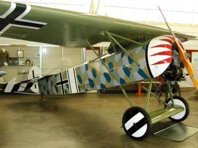
Scratch Build - Fokker DVIII 1/6 Scale Plans
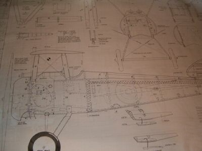
The real Fokker D VIII from the side.
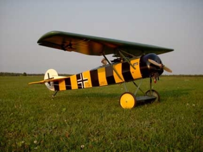
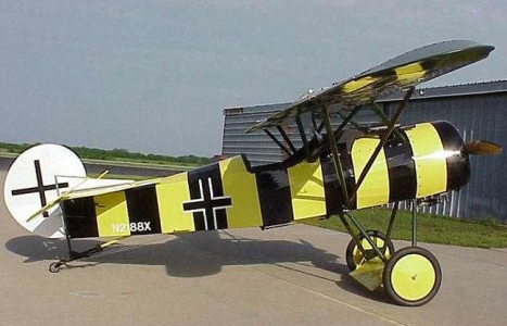
Fokker D VIII RC model.
During the closing weeks of the first World War there appeared over the front lines a nimble little monoplane that is generally credited as being the finest fighter of its day. This was the famous Fokker D-8 of the German Imperial Air Force.
Powered by a rotary Oberursel engine of 110 horsepower, the D-8 had a speed of 115 m.p.h. It climbed at a rate of 1,500 ft per min. and could ascend over four miles. In the ability to maneuver and dive it was unexcelled. So superior was the performance of this ship that it would have been a tremendous blow to tile Allied air forces had any, great number been completed before the war's end.
In early 1918, Fokker produced several rotary-powered monoplane designs. Of these, Fokker submitted the V.26 and V.28, small parasol-winged monoplanes with his usual steel-tube fuselages, for the second fighter trials at Adlershof in May/June 1918. The V.28 was tested with both the 145 hp Oberursel UR.III and 160 hp Goebel Goe.III, though neither of these engines were ready for operational service.
The V.26 utilized the standard Oberursel UR.II engine, producing only 110 hp. While this engine was obsolete, the V.26's low drag and light weight meant the V.26 was nevertheless quite fast. The Fokker designs were only barely beaten by the Siemens-Schuckert D.III with the complex contra-rotary Siemens-Halske Sh.III engine.
The Fokker D VIII in camouflage.
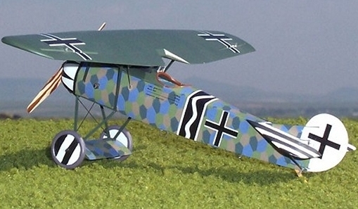
Fokker D VIII model in camouflage.
Specifications:
Wingspan: 57 in (approx. 1430mm)
Fuselage Length: 40in. (approx. 1000mm)
Weight: 1800gr
Motor Size: 0.40cu.in. - 0.60cu.in. 2-str / .40 - .70 4-str
RC- Functions: Rudder, Throttle, Elevators, Ailerons
The model is in 1/6 scale and will probably fly the best with a small sized 4 stroke engine, maybe a O.S 26 FS or the old O.S FS 40 which I have.
The Fokker DVIII is to be built from free flight plans from 1941. I am thinking about alterer this set of free flight plans into RC control. These plans can be downloaded from these two pages: page1 and page2. if you think about doing the same yourself.
Also visit this link where this model is with info if you think about looking into these drawings.
Here is a clip, showing a similar size Fokker DVIII on its maiden flight. Or this clip with a slightly bigger model.
The Fokker E.V was a parasol-monoplane fighter aircraft designed by Reinhold Platz and built by Fokker-Flugzeugwerke. It entered service with the Luftstreitkräfte in the last months of the First World War. After several fatal accidents due to wing failures, the aircraft was modified and redesignated Fokker D.VIII.
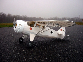
Scratch Build - Culver Cadet Plans
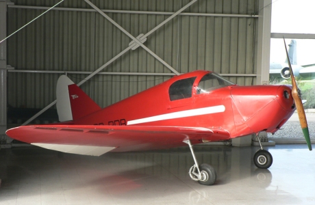
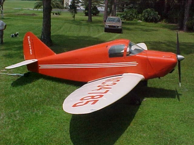
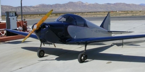
The real Culver Cadet from 1941 sideview.
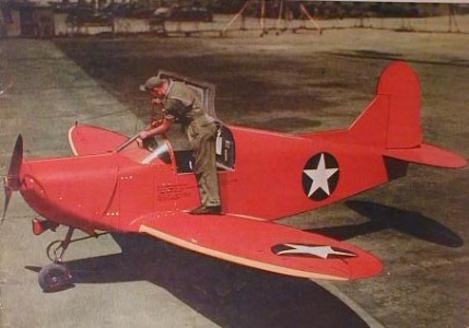
The full size Cadet with remote control ordered by the US army.
Culver Cadet as a RC Model.
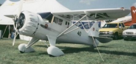
The Culver Cadet was the brainstorm of Al Mooney. Walter Beech was the Culver plant manager during it's inception,this explains why the Culver Cadet was one of the fastest airplanes in its category, the two-place Cadet was a favorite among sportsman pilots who demand extra speed and performance.
In August 1940, the U.S. Army Air Corps issued a requirement for a small radio-controlled aircraft for use as a target for anti-aircraft gunnery practice. Culver submitted a drone variant of their Cadet LFA sports plane, which was subsequently ordered by the USAAC in two versions, the A-8 powered by a Franklin O-200 piston engine, and the A-8A with a more powerful Lycoming O-290. In June 1941, the A-for-Aerial Target category was dropped because of possible confusion with the A-for-Attack series.
The A-8 and A-8A became the PQ-8 and PQ-8A, respectively, and the prototype of the Cadet target was designated as XPQ-8. The PQ category designated targets with a provision for manned flight, and because PQ-8 was the first allocation in the series, numbers PQ-1 through -7 remained unassigned.
Read more about the Culver Cadet on this magnificent webpage.
A beautifully restored Cadet by the gas pump.
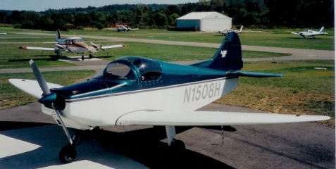
1966 Culver LAR 90, an evolution of Al Mooneys Culver Cadet.
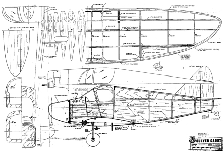
Culver Cadet plans.
Specifications:
Wingspan: 58 in (approx. 1450mm)
Fuselage Length: 38 7/8in. (approx. 948mm)
Weight: approx 2000gr
Motor Size: 0.40cu.in. - 0.60cu.in. 2-str / .40 - .70 4-str
RC- Functions: Rudder, Throttle, Elevators, Ailerons
The model is in 1/6 scale and will probably fly the best with a medium sized 4 stroke engine, maybe a O.S FS 40 or similar. The plans for this plane is traditional and is based on balsa and plywood, drawings is by Frank Capan. The fuselage is simple and boxy but the elliptical wing is really sleek and pretty which makes for an interesting contrast.
The Cadet was used by the US army as a RC plane in scale 1:1 as target practice. So this might be the ultimate remote controlled model!
Speaking of scale 1:1, here is a rather wonderful video of two Culver Cadets flying in formation.
Scratch Build - F4u 1D Corsair Plans
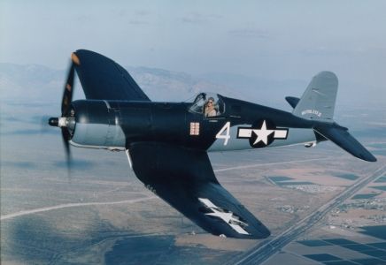
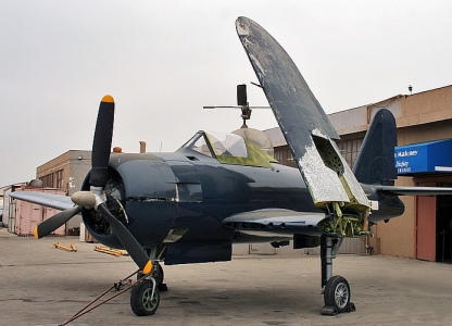
The real F4u Corsair in flight.
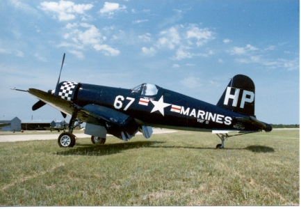
F4u Corsair in Marine Colors.
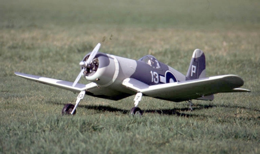
Corsair as a RC Model in US Army Colors.
The Chance Vought F4U Corsair was an American fighter aircraft that saw service in World War II and the Korean War (and in isolated local conflicts). Goodyear-built Corsairs were designated FG and Brewster-built aircraft F3A. The Corsair served in some air forces until the 1960s, following the longest production run of any piston-engined fighter in history (1940 - 1953). During World War II, it was the fighter the Japanese feared the most. The US Navy counted the average kill-rate as for every F4U shot down, 11 enemy aircraft were shot down. It had a turbocharged engine, which made a whistling sound when it was in the air. The Japanese nicknamed it "Whistling Death".
The Corsair started life as the result of a U.S. Navy requirement for a carrier aircraft which could match the performance of the best land and carrier-based fighter planes. Designed in 1938 by Rex Biesel, the first prototype Corsair designated XF4U-1 first flew on 29 May 1940. When flown in 1940, the XF4U-1, powered by a Pratt & Whitney R-2800 Double Wasp radial engine, became the first U.S. single-engine production aircraft capable of 400 mph (640 km/h) in level flight. It was a remarkable achievement for Vought, as compared to land-based counterparts, carrier aircraft are "overbuilt" and heavier to withstand the extreme stress of deck landings.
F4u Corsair start up video, and a video of a Corsair Fly By.
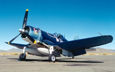
F4u Corsair on the ground.
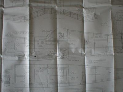
F4u Corsair Plans.
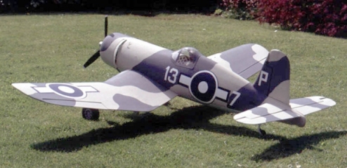
F4u Corsair as a model in US Army Colors.
Specifications:
Wingspan: 56 in (approx. 1400 mm)
Fuselage Length: 47in. (approx. 1170 mm)
Weight: approx 2000gr
Motor Size: 0.35 / 0.46 two stroke or 0.48 / 0.70 four stroke
RC- Functions: Rudder, Throttle, Elevators, Ailerons, Flaps
The model is in 1/8 sport scale and for sound, a 4 stroke engine will suit the best in my opinion.
The plans for this plane is traditional and is based on balsa and plywood, drawings is by Michell Faizandier.
RC F4u Corsair flying, But why go RC? Make a 1/2 Scale F4u Corsair and fly it yourself!
Scratch Build - Ryan FR-1 Fireball Plans
Ryan FR-1 Fireball awaiting restoration.
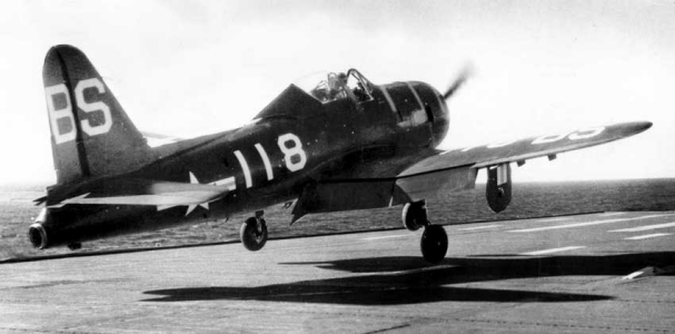
A Ryan Fr-1 taking off from USS Ranger.
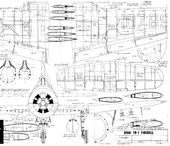
Ryan FR-1 Plans.
The FR-1 "Fireball" was designed in early 1943 for the US Navy, from a proposal by Admiral J McCain for a composite powered fighter in December 1942. At the time this was seen as the way ahead for the US Navy as early the jet engines had sluggish acceleration which required a long take off run, which was fine on dry land, but understandably gave rise to some concern when using aircraft from carriers. On the 1/2/1943 The Ryan Aeronautical Company was awarded a contract for three prototypes and one static airframe for testing. The first aircraft was ready for it's maiden flight on the 25/6/1944, however it was only powered by it's piston engine for the first two flights with the General Electric I -16 turbojet engine being fitted a few days later.
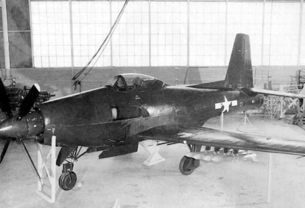
One of the 66 Ryan Fr-1 which where built.
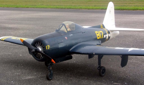
Ryan FR-1 Fireball as a RC Model.
Ryan FR-1 Firebird in Navy Colors.
Specifications:
Wingspan: 60 in (approx. 1500 mm)
Fuselage Length: 48in. (approx. 1210 mm)
Weight: approx 3300gr
Motor Size: 0.35 / 0.46 two stroke
or 0.48 / 0.70 four stroke + electrical ducted fan
RC- Functions: Rudder, Throttle, Elevators, Ailerons
The model is in 1/8 scale, and the plans for this plane is traditional and is based on balsa and plywood, drawings is by W. A. Octzell.
The most interesting feature of the Ryan FR-1 is that it has double engines. One radial engine up front and a J-31 jet engine in the back. I guess having a glow engine in the front, and an electrical ducted fan set up in the rear would provide quite a few excellent fly by's with apparent dead stick when engine up front is turned off!
Scratch Build - DeHavilland DH88 Comet Plans
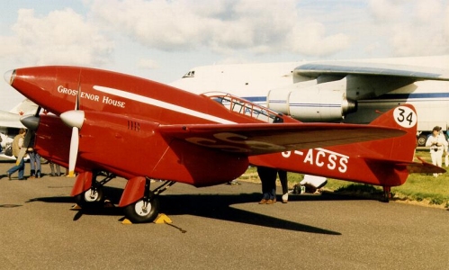
The original DH88 Comet - Grosvenor House.
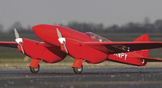
The DH88 Comet as a model.
In 1934 Sir MacPherson Robertson offered a prize of £10,000 for the winner of an air race from England to Australia to mark the centenary of the foundation of the State of Victoria. Most entrants for the race were in existing aircraft designs, however de Havillands wanted to win the race and so designed an aircraft for this purpose, work starting in February. The DH88 was designed, built and flown in a total time of nine months to enter and win the MacRobertson Air Race in October of 1934. Three orders for DH88s were received: G-ACSR was painted green and raced by Owen Cathcart-Jones and Ken Waller on behalf of Bernard Rubin; G-ACSP was painted black and gold and was named 'Black Magic', it was owned and raced by Jim and Amy Mollinson; the third Comet to be entered was G-ACSS painted scarlet and named 'Grosvenor House' it was entered by the hotel's managing director A. Edwards. For the race the pilots of G-ACSS were C.W.A. Scott and Tom Campbell-Black. In the race G-ACSS arrived first in Australia and qualified for both prizes, one for fastest speed and one for the handicap race; however the race rules prevented both prizes being awarded to the same aircraft and so G-ACSS only received the main speed prize. Of the other Comets G-ACSR finished fourth and left for England as soon as it arrived carrying news-reels of the event. On its return it had set a new out-and-back record arriving back at Mildenhall thirteen and a half days after it left at the start of the race. G-ACSP retired from the race with engine trouble.
The DH Comet G-ACSS Grosvenor House survives, it is in the Shuttleworth Collection at Old Warden in Bedfordshire, England. It is talk of it flying again.
Original footage from 1934 from the race, a must see. Listen to the sound of the engines in this Comet take off!
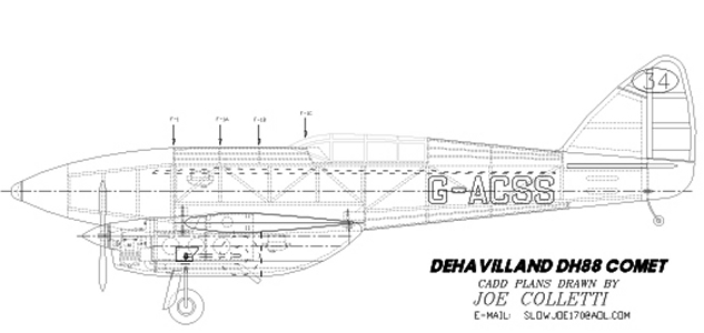
DH88 Comet Plans.
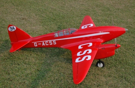
DH88 Comet, smaller model.
Specifications:
Wingspan: 93 in (approx. 2330 mm)
Fuselage Length: 47.5 in. (approx. 1190 mm)
Weight: approx 6800gr
Motor Size: Two engines: 0.46 / 0.70 two stroke
or two 0.60 / 0.90 four stroke
Electrical set up also possible
RC- Functions: Rudder, Throttle, Elevators, Ailerons, Flaps
The model is in 18% scale, and the plans for this plane is traditional and is based on balsa and plywood, drawings is by Joe Coletti.
The DH88 is known to be a handful to fly. So also with the model apparently. Here is a link from a maiden flight with a electrical setup Comet. A similar plane can be seen here. But equipped with double glow engines is my favourite.
This model is large enough to sport goodies like retractable wheels. And the engine pods are more than big enough to hide both wheels and have hatches. In the nose of the Comet, orginally there was a landing light. If or when I build this model, this light will ofcourse have light inside. This airplane makes a hansome and very special looking model. And the history behind the plane is very interesting. Iin the mid 30, flight speed records made a frenzy all over the world. Everyone was talking about flight innovations and speed records. And this airplane was specially made in order to take one special speed record, which it achieved.
About engines, maybe a double set of O.S AX 46 or two O.S 46 LA will do.
Scratch Build - DeHavilland DH.100 Vampire Plans
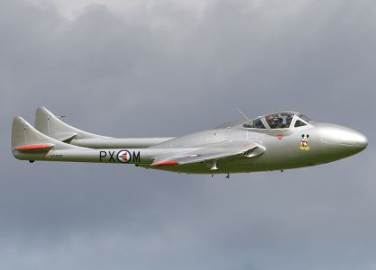
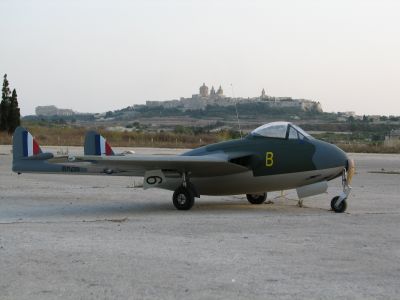
A Norwegian De Havilland DH 100 Vampire in flight.
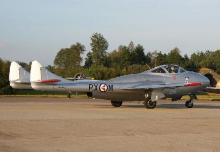
The Vampire has parked.
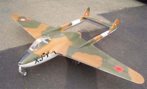
The De Havilland DH 100 as a model.
The Vampire began as an experimental aircraft, unlike the Gloster Meteor which was always specified for production. Under specification E.6/41, design work on the DH-100 began at the de Havilland works at Hatfield in mid-1942, two years after the Meteor.
Originally named the "Spider Crab," the aircraft was entirely a de Havilland project, exploiting the company's extensive experience in using moulded plywood for aircraft construction, as used in the Mosquito bomber. It was the last time composite wood and metal construction was used in high performance military aircraft. It had conventional straight mid-wings and a single jet engine placed in an egg-shaped, aluminium-surfaced fuselage exhausting in a straight line. To reduce the losses caused by a long jetpipe the designers used the distinctive tail with twin booms, similar to that of the Lockheed P-38.
Geoffrey de Havilland Jr, the de Havilland chief test pilot and son of the company's president, test flew prototype LZ548/G on its maiden flight 20 September 1943 from Hatfield. The flight took place only six months following the Meteor's maiden flight. The first Vampire flight had been delayed due to the need to send the sole remaining flight engine to Lockheed to replace one destroyed in ground engine runs in the prototype XP-80. The production Vampire Mk I did not fly until April 1945 with most built by English Electric Aircraft due to the pressures on de Havilland's production facilities, busy with other types. Although eagerly taken into service by the RAF, it was still being developed at war's end, consequently the Vampire never saw combat in the Second World War. A total of 3,269 Vampires were built in the UK, and about 1,100 in other countries although there is some uncertainty about the numbers built in Italy. There were 15 versions, e.g. a twin seated night fighter, trainer and carrier-based aircraft.
Here is a link to a Norwegian Vampire doing low passes and acrobatics at an Air Show in Ski 1992. The Vampire had very poor acceleration and this is visible in this film where the take off length is rather long.
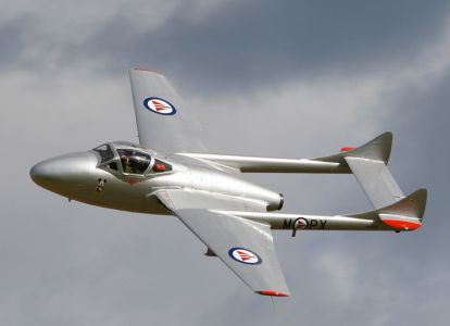
A Norwegian DH 100 Vampire.
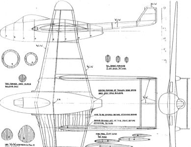
De Havilland DH 100 Vampire plans.
The model is VERY true to the real aircraft.
Specifications:
Wingspan: 38 in (approx. 966 mm)
Fuselage Length: 30 in. (approx. 750 mm)
Weight: approx 1100gr
Motor Size: Electrical ducted fan
RC- Functions: Rudder, Throttle, Elevators, Ailerons
The model is in 1/12 scale, and the plans for this plane is traditional and is based on balsa and plywood, drawings is by Howard Boyd.
The DH100 was in it's days rather underpowered. The model will not be with a ducted fan setup. Here is a link to a similar airplane, taking off from a RC field. The De Havilland DH 100 and DH115 (two seater) is very nice models with a rather different looks than most planes. Here is a video of Radio Controlled airplanes, including a Vampire ending a local airshow.
The Vampire I will make will be a very scale model from the norwegian plane in the top pictures of this plane.
The Vampire it unusual in design, and when the first mass produced aircraft flew in 1946, this plane was considered very modern and state of the art.
The plane was used by some 31 air forces. Of the major Western powers, Germany, Spain and the US were the only ones not to use the aircraft type.
The photos of the Norwegian Vampire LN-DHZ / PX-M is taken by Tom A. Paulsen. The pictures are of an extreme quality and very well made. I have cropped the images to fit the design on my page.